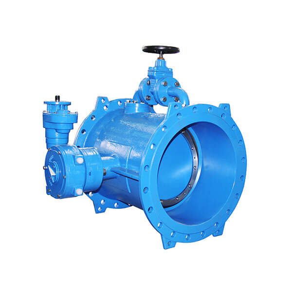
ZHENGZHOU, HENAN, CHINA, October 23, 2026 /EINPresswire.com/ — In large-scale municipal water networks and heavy industrial pipelines, managing high differential pressure during valve operation remains a persistent technical challenge. Standard large-diameter valves often experience excessive seat friction, torque spikes, and rapid seal degradation when opened under full line pressure. To address these operational demands, engineers increasingly turn to specialized bypass systems. As a dedicated Solutions Provider of High Quality Butterfly Valve With Bypass, NST engineers flow management solutions that integrate a secondary smaller-bore line around the primary valve disk. This configuration balances differential pressure across the main closure prior to operation, dramatically reducing operating torque, preventing water hammer, and protecting primary sealing surfaces. Understanding how this integrated bypass mechanism works-and how precision manufacturing achieves zero-leakage performance-is critical for procurement specialists and pipeline engineers seeking long-term system integrity.
The Engineering Logic: Resolving High-Differential Pressure and Sealing Integrity
Industrial fluid transport systems present severe operating conditions where static head pressure creates immense force against closed valve disks. When field operators attempt to actuate an unassisted large-diameter valve against high differential pressure, several mechanical failure modes can occur.
High Actuation Torque: Opening a large disk directly against high upstream pressure requires substantial mechanical effort, often demanding oversized, costly electric or hydraulic actuators.
Premature Seat Wear: High friction during the initial unseating motion strips away resilient elastomer or metal seating surfaces, causing internal downstream leakage.
Hydraulic Shock and Water Hammer: Sudden pressure drops during quick unseating generate severe pressure surges, damaging upstream piping, instrumentation, and pump assemblies.
Cavitation and Noise: High-velocity fluid rushing through a micro-gap during partial opening creates localized vapor bubbles that collapse destructively against the valve body.
Technical Solution: The Bypass Balance and Zero-Leakage Architecture
Integrating a bypass assembly fundamentally changes the pressure dynamics during actuation. The bypass line, controlled by an auxiliary valve, opens first to allow controlled fluid passage into the downstream section. As fluid fills the downstream cavity, the differential pressure across the main disk equalizes.
Closed State: Upstream pressure remains high while downstream pressure is low. Both the main disk and the bypass valve remain fully sealed.
Bypass Equalization: The auxiliary bypass valve opens first, allowing fluid to flow downstream to equalize pressure across both sides of the main disk.
Main Valve Open: Once pressure parity is established, the primary actuator opens the main disk smoothly under near-zero differential conditions.
Once pressure parity is established, the primary actuator opens the main disk under near-zero differential conditions. This mitigation eliminates excessive torque spikes and severe mechanical shear on the seating materials.
To achieve continuous zero-leakage performance, valve geometry and material selection must work in unison. Modern high-performance designs utilize double or triple eccentric shaft offsets. These offsets lift the sealing ring off the body seat almost instantly upon rotation, eliminating rubbing across the 360-degree contact circumference. Combined with precision-machined stainless steel seating rings, resilient EPDM/NBR inserts, or laminated metal-to-metal seals, the structure maintains tight bi-directional sealing even under fluctuating thermal and pressure cycles.
Key Technical Parameters and Selection Criteria for Procurement
Selecting the correct valve configuration requires evaluating multiple physical, material, and operational parameters to align with specific job site conditions.
Matching Specifications to Regional Operating Conditions
Pipeline networks in North America and Europe often demand strict adherence to standards such as EN 593, AWWA C504, and ISO 5752, along with drinking water certifications including NSF/ANSI 61 or WRAS. In the Middle East and Southeast Asia, where desalination, ambient high temperatures, and high-salinity coastal environments prevail, material selection emphasizes duplex stainless steel trim, external anti-corrosion epoxy coatings applied via electrostatic fusion bonding (FBE), and specialized marine-grade hardware.
Core Manufacturing Capabilities and Technical Innovations
Delivering consistent zero-leakage performance across high-volume infrastructure projects requires robust manufacturing quality control and proven engineering heritage. Originating in Zhengzhou, Henan Province, Newstar Valve (Zhengzhou) Co., Ltd.-operating under the brand NST (formerly ZD)-has developed comprehensive flow service solutions to resolve critical industrial fluid control challenges. In China’s municipal water treatment sector, NST valve solutions have established a leading market presence, occupying over 40% market share in municipal water distribution and treatment projects.
The manufacturing process incorporates advanced CNC machining centers to ensure tight geometric tolerances on valve bodies, disks, and eccentric shafts. Every disk sealing profile undergoes multi-axis machining to achieve seamless contour uniformity. To ensure structural integrity, hydrostatic testing and double-block seating tests are executed according to EN 12266-1 and ISO 5208 standards prior to shipment.
Engineering teams apply advanced Computational Fluid Dynamics (CFD) modeling to analyze internal flow velocities and optimize bypass manifold geometry. This design step minimizes turbulent eddies, prevents localized cavitation, and lowers overall flow resistance coefficients ($K$-value). For verified engineering implementations, technical reviewers can examine detailed product case evaluations such as the Butterfly Valve With Bypass Case Study, which demonstrates field installation performance, pressure drop metrics, and system integration specs.
NST maintains a sales and service network across Chinese municipalities and capital cities, backed by international sales organizations in North America, Europe, Italy, the Middle East, Central Asia, and Africa, delivering tailored technical guidance directly to project sites worldwide.
Frequently Asked Questions (FAQ)
What is the main purpose of a bypass on a butterfly valve?
A bypass line allows fluid to pass around a closed main valve disk to balance pressure upstream and downstream before opening. This reduces operating torque, minimizes seat wear, and prevents destructive water hammer in high-pressure piping systems.
How does pressure equalization achieve zero leakage over long operational lifespans?
By equalizing pressure via the bypass prior to main disk rotation, the resilient or metal seating surfaces do not suffer intense frictional tearing during unseating. Preserving seat geometry ensures the valve maintains a complete bi-directional seal without bypass leakage over thousands of operating cycles.
Can a butterfly valve with bypass be used for bi-directional flow?
Yes, high-performance double offset and triple offset butterfly valves paired with bi-directional bypass lines are engineered to seal equally well against pressure from either direction, making them suitable for complex loop distribution networks.
What certifications should I check for municipal drinking water applications?
For potable water projects, procurement specialists should verify drinking water safety approvals such as WRAS, NSF/ANSI 61, or DVGW, along with quality and pressure testing compliance according to ISO 9001, EN 12266-1, and API 598 standards.
How do I select the right bypass valve size relative to the main valve diameter?
Standard practice dictates selecting a bypass diameter roughly 10% to 15% of the main valve nominal diameter (for example, a DN100 bypass on a DN800 main valve). However, exact sizing depends on system flow rate, pipe volume, allowable pressure equalization time, and maximum system working pressure.
What maintenance is required for the bypass manifold assembly?
Routine maintenance involves checking the primary actuator gearboxes, inspecting external bypass piping joints for flange leakage, verifying auxiliary valve seating integrity, and periodically flushing the bypass line to prevent debris buildup.
Project Technical Specification and Engineering Support
When designing high-pressure transmission mains, municipal water treatment facilities, or industrial cooling loops, specifying the correct valve configuration early prevents costly field modifications and unplanned system shutdowns. Engineering teams require precise flow calculations, face-to-face dimensions, actuator torque ratings, and material compatibility data matched to specific fluid parameters.
For custom engineering inquiries, detailed dimensional CAD drawings, project specification sheets, or site-specific flow control consulting, technical teams can access complete product guidelines and contact application engineers directly through the official website at https://www.nstvalves.com/
NST
NST
Legal Disclaimer:
EIN Presswire provides this news content “as is” without warranty of any kind. We do not accept any responsibility or liability
for the accuracy, content, images, videos, licenses, completeness, legality, or reliability of the information contained in this
article. If you have any complaints or copyright issues related to this article, kindly contact the author above.

Media gallery